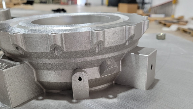
Rocket engines are fiery, noisy, and highly pressurized, requiring every component to endure all three. This meant a complex process of machining, welding, and brazing for decades, with one single error potentially delaying the project by months. However, metal additive manufacturing is changing all of that. Instead of cutting a design down to what a machine can make, engineers can now print shapes that used to be out of reach.
Why Rocket Engines Were Hard to Build With Traditional Manufacturing Methods
A traditional engine is built from a lot of pieces. A single injector can be made of many small parts that are machined, cleaned and then joined by welding or brazing. Every joint is a place where something can leak or crack. And every extra step adds weeks.
Testing made it worse. If a test fire showed a problem, the fix often meant new tooling and a long wait. Small teams couldn’t afford many rounds of that. Changing a design on paper was easy. Changing the hardware was slow and expensive.
Design Changes That Metal Additive Manufacturing Makes Possible
Printing changes the design in a few big ways:
- Cooling channels inside the walls. Fuel can flow through winding passages to soak up heat, and printing builds those passages directly instead of drilling or joining them.
- Fewer parts. An assembly that once needed many pieces can often be printed as one, which removes joints and leak paths.
- Built-in plumbing. Manifolds and mounting features can be part of the same piece.
- Faster test cycles. A revised design can go from file to hardware without new tooling.
- Weight savings. Material goes only where the loads need it, which matters when every kilogram counts.
Materials That Matter in Printed Rocket Hardware
Two metals come up most. Inconel 718 is a nickel alloy known for holding its strength at high temperatures, so it shows up in hot structures and turbomachinery parts. GRCop-42 is a copper alloy developed at NASA’s Glenn Research Center. Copper moves heat very well, which makes this alloy a good fit for combustion chamber liners and injectors that have to shed heat quickly.
Post-Processing and Quality Challenges That Engineers Still Have to Solve
Printing isn’t a magic fix. The internal surface of the printed channel is very rough, and the roughness influences the flow dynamics and heat transfer processes. The loose powders may accumulate in the narrow channels and should be removed. Small pores may exist in the material, and this is the reason why most of the important elements undergo hot isostatic pressing.
Finishing is a real part of the job. A GRCop-42 fuel injector shown at the RAPID + TCT conference makes the point. In Space designed it, AME printed it, and REM finished the surface, with a focus on granular roughness and the oxide left behind by hot isostatic pressing. Three companies, one part, and each step mattered.
How Additive Manufacturing & Engineering Supports Aerospace and Propulsion Work
Additive Manufacturing & Engineering, known as AME, is a metal printing shop in Huntsville, Alabama. The company says it has printed many parts for NASA over the years, including a first-of-its-kind rocket part made in partnership with Marshall Space Flight Center. It also worked with Mountain Aerospace Research Solutions to take the MK2X propulsion part from design to hardware.
AME prints on an EOS M400 with a build volume of up to 400 mm per side, and works in Inconel 718 and GRCop-42. It accepts STL, STP and OBJ files and checks designs for printability, though it doesn’t design parts from scratch. The company is AS9100D and ISO 9001 certified and ITAR registered, which matters on propulsion work.
What Rocket Teams Should Prepare Before Sending a Part for Printing
A few things save time when they’re ready up front:
- A 3D file in STL, STP or OBJ format
- The alloy and any property requirements
- Surface finish needs, especially inside flow passages
- Post-processing and inspection steps, such as heat treatment or hot isostatic pressing
- Export and certification requirements, including ITAR
- Quantity and schedule
FAQs
Why is metal additive manufacturing useful for rocket engines?
It allows the creation of complicated shapes that cannot be machined. Components that previously had multiple parts now may be manufactured in a single unit, thus reducing the number of joints prone to leakage. The ability to change hardware quickly without having to change the tooling is another advantage of 3D printing.
Which rocket engine parts are being 3D printed?
Injectors, combustion chamber liners, nozzles and turbopump components are common examples, along with brackets and manifolds. Teams tend to start with parts where complex internal shapes save the most effort. Each part still needs testing and inspection before it flies. That testing is not optional.
What is GRCop-42 and why is it used in printed engine parts?
The GRCop-42 is a copper alloy invented by NASA’s Glenn Research Center. The alloy maintains its strength under high temperatures. The material dissipates heat quickly as it is made up of copper. Therefore, it works well for combustion chamber liner and injector applications.
What are the biggest challenges of printing rocket engine parts?
Surface roughness inside flow passages, trapped powder in narrow channels, and tiny internal pores are the main ones. Many parts go through hot isostatic pressing and careful finishing to fix them. Qualification is another hurdle, since flight hardware needs proof that every printed part meets strict standards.
How big of a rocket part can be printed on a metal 3D printer?
It depends on the machine. Systems like AME’s EOS M400 handle parts up to about 400 mm in each direction. Bigger components are usually printed in sections and joined, or made by other methods. Teams should check the build volume with the provider before finishing a design.